Fluke 77 Multimeter: A Comprehensive Guide (Manual Focus)
Welcome! This guide unlocks the Fluke 77’s potential, fostering creativity and innovation through detailed exploration of its functions and safe operational practices.
The Fluke 77 Multimeter stands as a cornerstone for professionals and enthusiasts alike, offering reliable and accurate electrical measurements. This versatile instrument is designed for a wide array of applications, from basic electrical troubleshooting to complex circuit analysis. Its robust construction and user-friendly interface make it an ideal choice for field service technicians, electricians, and hobbyists.
This manual serves as a comprehensive guide to understanding and utilizing the full capabilities of your Fluke 77. We’ll delve into its features, functions, and safety precautions, ensuring you can confidently and effectively employ this tool in your work. Exploring new possibilities is at the heart of the Fluke 77 experience, and this manual will help you unlock its full potential for creativity and innovation.
Safety is paramount when working with electrical systems. Always adhere to the general safety guidelines outlined in this manual to prevent injury and ensure accurate measurements.
Key Features and Specifications
The Fluke 77 boasts a range of features designed for precision and ease of use. It offers accurate voltage and current measurements, alongside resistance, continuity, and diode testing capabilities. Auto-ranging functionality simplifies measurements by automatically selecting the appropriate range, while the data hold function freezes readings for convenient recording.
Key specifications include: DC Voltage accuracy of ±0.5%, AC Voltage accuracy of ±1.0%, DC Current accuracy of ±1.0%, and Resistance accuracy of ±0.5%. The multimeter features a large, easy-to-read digital display and is built to withstand demanding field conditions. Its compact size and lightweight design enhance portability.
Furthermore, the Min/Max/Average recording function captures fluctuations in measurements, providing valuable insights into circuit behavior. The Fluke 77 is a dependable tool, built for lasting performance and designed to empower users with reliable data.
Understanding the Fluke 77 Interface
Navigating the Fluke 77 is straightforward. This section details the front panel controls, display symbols, and input jacks, ensuring optimal understanding and efficient operation.
Front Panel Overview & Controls
The Fluke 77’s front panel is intuitively designed for ease of use, even in challenging environments; Central to the layout is the large, easily readable digital display, providing clear and accurate measurements. To the right of the display, you’ll find the function selector rotary switch. This dial allows you to choose from a variety of measurement modes, including AC/DC voltage, AC/DC current, resistance, continuity, and diode test.
Below the display are several key buttons. The ‘Range’ button enables manual ranging, offering precise control over measurement resolution. The ‘Hold’ button freezes the current reading on the display for convenient recording. Further controls include the ‘Min/Max/Avg’ button, which captures the minimum, maximum, and average values over a specified period. Input jacks, strategically positioned at the bottom of the panel, accommodate test leads for various measurements. Understanding each control’s function is crucial for maximizing the Fluke 77’s capabilities and ensuring accurate results.
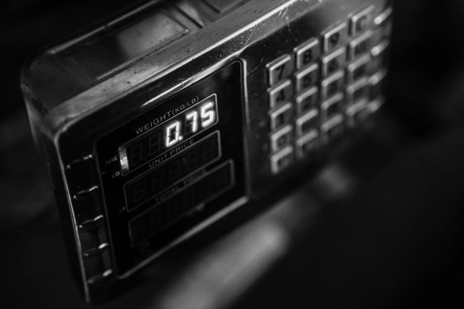
Display Symbols and Readings
The Fluke 77’s display utilizes a variety of symbols to convey crucial information alongside numerical readings. The primary display area shows the measured value, with the appropriate unit (Volts, Amps, Ohms, etc.) clearly indicated. A ‘DC’ symbol signifies direct current measurements, while ‘AC’ denotes alternating current. An overload indication, typically represented by ‘OL’, appears when the measured value exceeds the meter’s range.
A low battery symbol alerts you when the battery needs replacement, ensuring continued accurate operation. The ‘Hold’ symbol illuminates when the data hold function is active, freezing the current reading. During resistance or continuity testing, the display shows the resistance value or beeps to indicate continuity. Understanding these symbols is vital for correctly interpreting measurements and avoiding misinterpretations. Familiarize yourself with each indicator to fully leverage the Fluke 77’s diagnostic capabilities and ensure reliable results in all your testing scenarios.
Input Jacks and Their Functions
The Fluke 77 features several input jacks, each designed for specific measurement types. The ‘COM’ (Common) jack serves as the reference point for most measurements and should always be connected first. The ‘VΩmA’ jack is used for voltage, resistance, and low current (milliamps) measurements. Connecting the test leads to this jack allows for a wide range of general-purpose testing.
For higher current measurements (Amps), utilize the dedicated ‘10A’ jack. Important: Never connect test leads to both the ‘VΩmA’ and ‘10A’ jacks simultaneously, as this can damage the meter. The input impedance is crucial for accurate readings; the Fluke 77 provides high impedance for voltage measurements to minimize circuit loading. Proper connection of test leads to the appropriate jacks is paramount for safe and accurate operation. Always double-check your connections before energizing the circuit to prevent damage to the meter or the device under test.

Measurement Capabilities
The Fluke 77 excels at AC/DC voltage and current measurements, resistance, continuity, and diode testing, providing versatile solutions for diverse electrical troubleshooting needs.
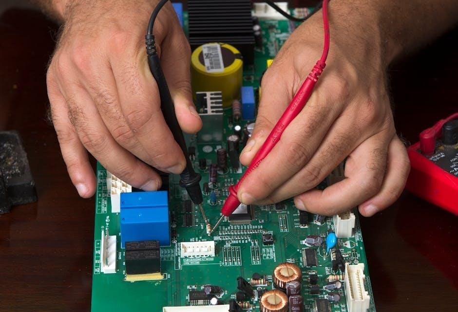
Voltage Measurement (AC/DC)
Measuring voltage with the Fluke 77 is a fundamental operation, covering both Alternating Current (AC) and Direct Current (DC) circuits. To measure DC voltage, select the DC voltage range on the rotary dial, connect the black test lead to the COM jack, and the red lead to the VΩ jack. Apply the probes across the circuit or component you wish to measure.
For AC voltage measurements, select the appropriate AC voltage range. The process for connecting the test leads remains the same. The Fluke 77 automatically ranges, simplifying the selection process, but manual ranging is also possible for specific applications. Always observe proper polarity when measuring DC voltage; reversed polarity will display a negative sign.
Important considerations: Ensure the selected voltage range is higher than the expected voltage to avoid overload. Be cautious when measuring high voltages, and always adhere to safety guidelines. The Fluke 77 provides accurate and reliable voltage readings, crucial for diagnosing electrical issues and verifying circuit performance.
Current Measurement (AC/DC)

Measuring current with the Fluke 77 requires a different setup than voltage measurements. Always remember that current measurements are performed in series with the circuit, meaning you must break the circuit to insert the multimeter. For DC current, select the DC current range, move the red test lead to the A jack (typically fused), and connect the black lead to COM.
To measure AC current, select the AC current range and follow the same connection procedure. Caution: Incorrect jack placement can cause damage to the multimeter or the circuit. The Fluke 77 offers various current ranges to accommodate different circuit characteristics. Auto-ranging simplifies the process, but manual selection provides greater control.
Safety is paramount: Start with the highest current range and work downwards to achieve optimal resolution. Never attempt to measure currents exceeding the multimeter’s maximum rating. Proper fuse protection is essential for safe current measurements.
Resistance Measurement
Measuring resistance with the Fluke 77 is straightforward, but requires the circuit to be de-energized. Power off the circuit and, ideally, disconnect the component you’re testing to ensure accurate readings. Select the resistance (Ω) range on the rotary dial. Insert the black test lead into the COM jack and the red test lead into the VΩ jack.
Touch the test leads to the component or points across which you want to measure resistance. The Fluke 77’s display will show the resistance value in ohms. Auto-ranging automatically selects the appropriate range, but manual selection offers precision. Important: Body resistance can affect low-resistance measurements, so avoid touching the metal parts of the test leads.
For higher resistance values, ensure good contact between the leads and the component. Note that resistance measurements can be influenced by temperature. Always document the measurement conditions for accurate comparisons.
Continuity Testing
Continuity testing with the Fluke 77 verifies electrical connection between two points. This is crucial for troubleshooting wiring, switches, and fuses. Select the continuity mode, often indicated by a diode symbol or a sound wave symbol, on the rotary dial. Connect the black test lead to the COM jack and the red lead to the VΩ jack.
Touch the test leads to the two points you want to test. If a complete circuit exists (low resistance), the Fluke 77 will emit an audible beep and often display a low resistance value. An open circuit (high resistance) will not produce a beep and will show “OL” (Over Limit) on the display.
Remember to de-energize the circuit before performing continuity tests. Continuity testing doesn’t indicate signal strength, only the presence or absence of a conductive path. It’s a quick and effective method for identifying broken wires or faulty connections.
Diode Test Function
The Diode Test function on the Fluke 77 allows you to check the functionality of diodes and other semiconductor devices. Select the diode test mode, typically represented by a diode symbol (arrow pointing to a vertical line), on the rotary dial. Connect the black test lead to the COM jack and the red lead to the VΩ jack.
A forward-biased diode will exhibit a voltage drop, typically between 0.5V and 0.8V, displayed on the multimeter. A reverse-biased diode should show “OL” (Over Limit), indicating infinite resistance. If a diode shows “OL” in both directions, it’s likely open or faulty. A shorted diode will show a low resistance (close to 0V) in both directions.
Important: Always test diodes in a circuit with power removed. This function can also be used to identify transistor junctions. Understanding diode behavior is essential for electronic repair and troubleshooting.
Advanced Features & Functions
Unlock precision! Explore auto-ranging, data hold, and min/max/average recording capabilities for detailed analysis and efficient troubleshooting with your Fluke 77.

Auto-Ranging Explained
Effortless Measurement: The Fluke 77’s auto-ranging feature dramatically simplifies measurements by automatically selecting the optimal measurement range for the input signal. This eliminates the need for manual range selection, reducing the potential for errors and saving valuable time. When activated, the multimeter intelligently assesses the signal’s magnitude and adjusts its internal settings accordingly, ensuring accurate readings across a wide spectrum of values.
How it Works: Instead of manually stepping through different ranges (like 200mV, 2V, 20V, etc.), the auto-ranging function continuously monitors the input. If the signal exceeds the current range’s capacity, the multimeter automatically shifts to a higher range, providing a reading within its limits. Conversely, if the signal is very small, it will downshift to a more sensitive range for improved resolution.
Benefits: Auto-ranging is particularly useful when dealing with unknown signals or rapidly changing values. It provides a convenient and reliable way to obtain accurate measurements without requiring prior knowledge of the expected signal level. This feature enhances usability and makes the Fluke 77 accessible to both novice and experienced users.
Data Hold Functionality
Capturing Transient Readings: The Fluke 77’s data hold function is invaluable for capturing and preserving a stable reading in situations where the measured value fluctuates or is difficult to observe directly. This feature “freezes” the current display reading, allowing you to record the value even after the input signal changes or you need to reposition the meter.
How to Use: To activate data hold, simply press the ‘HOLD’ button on the front panel. The display will show a ‘HOLD’ icon, indicating that the current reading is frozen. Subsequent changes to the input signal will not affect the displayed value. Pressing the ‘HOLD’ button again cancels the data hold function, returning the display to real-time measurements.
Practical Applications: This function is particularly useful when measuring signals in hard-to-reach locations, or when you need to focus on documenting the reading without constantly monitoring the display. It ensures accurate recording of transient or unstable measurements, enhancing the reliability of your results.
Min/Max/Average Recording
Tracking Measurement Variations: The Fluke 77 offers a powerful Min/Max/Average recording function, enabling detailed analysis of signal fluctuations over time. This feature automatically captures the minimum and maximum measured values, alongside the average reading, providing a comprehensive overview of measurement variability.
Activation and Operation: Initiate this mode by pressing the ‘MIN/MAX/AVG’ button. The meter cycles through displaying the minimum, maximum, and average values. An indicator on the display shows which value is currently being shown. Pressing the button again toggles between these three modes. To return to normal operation, press the button until the indicators disappear.
Beneficial Applications: This function is ideal for troubleshooting intermittent faults, monitoring signal stability, and identifying peak or valley values. It’s particularly useful in environments where continuous observation is impractical, providing a complete record of measurement behavior for thorough analysis and informed decision-making.
Safety Precautions & Maintenance
Prioritize Safety! Always adhere to general safety guidelines when operating the Fluke 77. Proper battery and fuse care ensures reliable performance and longevity.
General Safety Guidelines
Crucial Safety Measures: Before utilizing your Fluke 77, carefully review these essential safety guidelines to prevent electrical shock and ensure accurate measurements. Always inspect the test leads for any damage – cracks, fraying, or exposed metal – and replace them immediately if compromised. Never exceed the multimeter’s specified input limits, as this can damage the instrument and pose a safety hazard;
Working with High Voltage: When measuring high voltages, exercise extreme caution. Disconnect power to the circuit being tested whenever possible. If live measurements are unavoidable, maintain a safe distance and use insulated gloves and eyewear. Avoid touching any exposed metal parts of the test leads or the multimeter itself.

Environmental Considerations: Operate the Fluke 77 in a dry, well-ventilated environment. Avoid using it in areas with flammable gases or liquids. Keep the instrument clean and free from dust and moisture. Regularly inspect the battery compartment for corrosion. Remember, safety is paramount when working with electrical equipment.
Battery Replacement & Care
Maintaining Optimal Performance: Your Fluke 77 utilizes batteries to power its functions; proper replacement and care are vital for consistent accuracy. When the low battery indicator appears on the display, promptly replace all batteries with the correct type – typically 9V alkaline batteries. Avoid mixing old and new batteries, or different battery types.
Replacement Procedure: To access the battery compartment, locate the battery cover on the rear of the multimeter. Use a small screwdriver to carefully open the cover. Remove the old batteries and install the new ones, ensuring correct polarity (+ and -). Securely close the battery cover.
Prolonging Battery Life: To maximize battery life, turn off the multimeter when not in use. Avoid storing the instrument in extreme temperatures. If the multimeter will be stored for an extended period, remove the batteries to prevent corrosion. Regularly check the battery contacts for cleanliness.
Fuse Replacement Procedures
Protecting Your Investment: The Fluke 77 incorporates fuses to safeguard its internal circuitry from damage due to overcurrents. If a fuse blows, the multimeter will cease to function correctly. Never operate the instrument with a blown fuse or attempt to bypass the fuse.
Replacement Steps: First, disconnect all test leads from the multimeter. Locate the fuse compartment on the rear panel. Using a Phillips head screwdriver, carefully remove the compartment cover. Identify the blown fuse – it will have a broken filament.
Correct Fuse Specification: Replace the blown fuse with a fuse of the exact same type and rating. Using an incorrect fuse can create a safety hazard or damage the instrument. Reinstall the fuse compartment cover and tighten the screw. Always use authorized Fluke replacement fuses to ensure continued safety and performance.